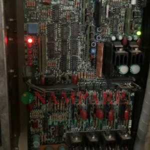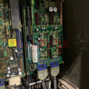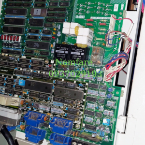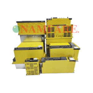


Mã lỗi của bo nguồn MDH CH Series
o. Name Details Cause of
occurrence Investigation method Remedy
11 Axis selection
error
The rotary switches are set
to the same value.
Otherwise, the switches
are set to an illegal value.
Axis No. setting is
incorrect.
Check the axis-No. setting for each unit. Set correctly.
12 Memory error 1 An error was detected in a Check the repeatability. Replace the unit.
memory IC or feedback IC
by self-check to be made
during the unit power ON.
CPU peripheral
circuit error Check the grounding state and ambient
temperature.
Improve the ambient
environment.
13 Software Check the repeatability. Replace the unit.
processing
error 1
Software operation
sequence error or
operation timing error
[Also detected while the
control axis is removed.]
CPU peripheral
circuit error Check the grounding state and ambient
temperature.
Improve the ambient
environment.
14 Software Check the repeatability. Replace the unit.
processing
error 2
An error was detected in
the current processing
circuit.
CPU peripheral
circuit error Check the grounding state and ambient
temperature.
Improve the ambient
environment.
Check SP205 = 0: Incomplete/
1: Completed
Carry out automatic
adjustment
16 Magnetic pole
position
detection error
Starting of the IPM spindle
was commanded before
positioning the magnetic
poles.
Automatic
adjustment has not
been completed. Check whether the unit has been replaced. Carry out automatic
adjustment
Check the repeatability.
(Occurs each time the power is turned ON)
17 A/D converter Replace the unit.
error
An error was detected in
the A/D converter for
current detection.
[Detected at power ON and
7s after ready OFF]
CPU peripheral
circuit error
Check the grounding state and ambient
temperature.
Improve the ambient
environment.
The detector input
connector is
disconnected.
Check the connector (CN2) connection.
Check the cable connection.
Connect correctly.
The detector cable
is broken.
Replace with the cable for another axis and
check the repeatability.
Replace the detector
cable.
Detector fault
18 Motor side
detector, initial
communication
error
Initial communication with
the detector was not
possible.
[Also detected when the
control axis is installed.]
Drive unit input
circuit fault
Exchange the detector and drive unit for
those of another axis and check the
repeatability. (Pinpoint the cause)
Replace the parts on
the side that caused
the alarm.
The detector input
connector is
disconnected.
Check the connector (CN3) connection.
Check the cable connection.
Connect correctly.
The detector cable
is broken.
Replace with the cable for another axis and
check the repeatability.
Replace the detector
cable.
Detector fault
1A Machine side
detector, initial
communication
error
Initial communication with
the detector cannot be
performed in the system
that uses OHA25K-ET or
high-speed serial detector
as the machine side
detector. (Refer to the
detector alarms list.) The unit input
circuit is broken.
Exchange the detector and drive unit for
those of another axis and check the
repeatability. (Pinpoint the cause)
Replace the parts on
the side that caused
the alarm.
The parameters are
set incorrectly.
The serial detector bit (SP034/bit8 =1) is
valid even through the serial detector is not
connected.
Set correctly.
1B Machine side
detector,
CPU error 1
In the high-speed serial
detector connected with
the machine side, an error
was detected in the data
stored in an EEPROM.
(Refer to the detector
alarms list.)
Refer to No. “1A”.
8. Troubleshooting
8 – 5
No. Name Details Cause of
occurrence Investigation method Remedy
1C Machine side
detector,
EEPROM/LED
abnormality
In the linear scale
connected with the
machine side, an error in
an EEPROM was detected.
Otherwise, in the
high-speed serial detector
connected with the
machine side, a
deteriorated LED was
detected.
1D Machine side
detector, data
error
In the high-speed serial
detector connected with
the machine side, an error
(a position error within one
rotation) was detected.
1E Machine side
detector,
memory error
In the linear scale
connected with the
machine side, an error on
ROM or RAM was
detected.
Otherwise, in the
high-speed serial detector
connected with the
machine side, the built-in
thermal protector
functioned.
1F Machine side
detector,
communication
error
In the high-speed serial
detector connected with
the machine side,
communication with the
detector stopped.
Refer to No. “1A”.
The detector input
connector is
disconnected.
Check the connector (CN2) connection.
Check the cable connection.
Connect correctly.
The detector cable
is broken.
Replace with the cable for another axis and
check the repeatability.
Replace the detector
cable.
Detector fault
20 Motor side
detector, No
signal 1
An error was detected in A,
B, Z-phase of the motor
side detector, or U, V,
W-phase.
Drive unit input
circuit fault
Exchange the detector and drive unit for
those of another axis and check the
repeatability. (Pinpoint the cause)
Replace the parts on
the side that caused
the alarm.
Z phase is not input
(Only spindle)
Check whether the Z phase is output within
3 rotations after orientation is started
Replace the PLG.
The spindle
parameter setting
is incorrect.
Check that SP037 bit-8 is set to “1”. Set correctly.
The detector input
connector is
disconnected.
Check the connector connected with the
detector.
Check the cable connection.
Connect correctly.
The detector cable
is broken.
Replace with the cable for another axis and
check the repeatability.
Replace the detector
cable.
Detector fault
Drive unit input
circuit fault
Exchange the detector and drive unit for
those of another axis and check the
repeatability. (Pinpoint the cause)
Replace the parts on
the side that caused
the alarm.
21 Machine side
detector, No
signal 2
An error was detected in
the A, B, Z-phase in a servo
closed-loop system.
Otherwise, an error was
detected in the A, B,
Z-phase in the spindle
encoder.
The spindle
parameter setting
is incorrect.
Check that SP037 bit-8 is set to “0”. Set correctly.
22 LSI error LSI operation error Check the repeatability. Replace the unit.
[Also detected while the
control axis is removed.]
Unit fault
Check the grounding state and ambient
temperature.
Improve the ambient
environment.
8. Troubleshooting
8 – 6
No. Name Details Cause of
occurrence Investigation method Remedy
The detector cable
is broken.
Replace with the cable for another axis and
check the repeatability.
Replace the detector
cable.
Occurs when the difference
between the speed
command and motor speed
is large. The spindle
parameter setting
is incorrect.
Check SP034, 040, 055, 257 and
following.
Set correctly.
If higher than 12 seconds, increase the
value.
Occurs during acceleration/ Set correctly.
deceleration.
Measure the
forward run →
reverse run time,
and reset SP055.
If less than 12 seconds, check the load
rate.
Reduce the load.
23 Excessive
speed
deflection 1
Occurs during cutting. Check the load
rate.
If higher than 120%, reduce the load. Reduce the load.
24 Ground fault A motor cable ground fault Drive unit fault Replace the unit.
was detected.
(Detected after emergency
stop have been released.)
Motor fault
Is the cable sheath damaged?
Replace the motor.
Battery voltage
drop
Check the battery voltage with a test.
(Occurs at 3 V or less)
Replace the battery
The communication
cable is incorrectly
connected or is
disconnected.
Check that the wiring between the unit and
battery unit is correct.
Connect correctly.
The battery line in
the detector cable
or communication
cable is broken.
Check the conductivity with a tester. Replace or correctly
wire the cable.
25 Absolute
position lost
The absolute position in the
detector was lost.
The detector cable
was disconnected
when the power
was turned OFF.
After alarm 18 has occurred, correctly
connect the detector cable and turn the
power ON again.
26 Unusable axis Check the repeatability. Replace the unit.
error
A power module error
occurred in the axis set as
the unusable axis “F”.
2-axis unit
dedicated alarm Check the grounding state and ambient
temperature.
Improve the ambient
environment.
27 Machine side Check the repeatability. Replace the detector.
detector, CPU
error 2
An error was detected in
the CPU for the linear scale
or serial detector.
The detector is
faulty. Check the grounding state and ambient
temperature.
Improve the ambient
environment.
28 Machine side Check the repeatability. Replace the detector.
detector,
overspeed
The linear scale speed
became to 45m/s or more
at the power ON.
A frequency signal
exceeding the tolerable
speed was detected.
The detector is
faulty. Check the grounding state and ambient
temperature.
Improve the ambient
environment.
29 Machine side Check the repeatability. Replace the detector.
detector,
absolute
position data
error
In the absolute position
linear scale, an error was
detected in the circuit.
Linear scale fault
Check the grounding state and ambient
temperature.
Improve the ambient
environment.
2A Machine side Check the repeatability. Replace the detector.
detector,
incremental
position data
error
In the incremental position
linear scale, an error was
detected in the circuit.
Linear scale fault
Check the grounding state and ambient
temperature.
Improve the ambient
environment.
2B Motor side
detector, CPU
error 1
Detector internal circuit
error
Detector fault Check the repeatability.
Check the ambient environment.
Replace the detector.
Review the ambient
environment.
2C Motor side
detector,
EEPROM/LED
error
EEPROM error was
detected in the motor side
linear scale. Also, the LED
in the detector has
deteriorated.
Detector fault (life) Check the repeatability.
Check the ambient environment.
Replace the detector.
Review the ambient
environment.
CAUTION Contact your nearest Service Center when an alarm not shown above occurs.
8. Troubleshooting
8 – 7
No. Name Details Cause of
occurrence Investigation method Remedy
2D Motor side
detector, data
error
Detector position data error
2E Motor side
detector,
memory error
ROM/RAM error was
detected in the motor side
linear scale.
Detector fault Check the repeatability.
Check the ambient environment.
Replace the
detector.
Review the ambient
environment.
The detector input
connector is
disconnected.
Connect correctly.
The detector cable
is broken.
Alarm 18 occurs when the power is turned
ON.
Check the connector (CN2) connection.
Replace the detector
cable.
Detector fault
Drive unit input
circuit fault
Alarm 18 occurs when the power is turned
ON.
Exchange the detector and drive unit for
those of another axis and check the
repeatability. (Pinpoint the cause)
Replace the parts on
the side that caused
the alarm.
Cable noise Is the cable shielded?
Is the cable wired in the same conduit as
the motor power line?
Review the cable
wiring and shield.
2F Motor side
detector,
communication
error
Communication with the
detector was cut off or
there was an error in the
received data.
Incorrect grounding Are the motor grounding and drive unit
grounding grounded separately?
Ground the motor
and drive unit at one
point.
The axis
specification
parameter (rapid)
setting is incorrect.
Check the machine specifications. Set correctly.
Check SV001 (PC1), SV002 (PC2), SV018
(PIT), SV025 (MTYP)
The parameter
setting is incorrect.
SP017 (TSP) or SP193 (SPECT)
Maximum speed: (SP017) × 1.15
Check Slimit.
Set correctly.
Is the speed loop gain too low? Adjust the gain.
Is the acceleration/deceleration time
constant too short causing the current to
be limited?
Increase the
acceleration/decele-r
ation time constant.
The speed is
overshooting.
Is the current limit value too low? Adjust the limit value.
31 Overspeed The motor speed exceeded
the tolerable value.
Detector fault Does the alarm occur when the power is
turned ON?
Change with another axis and check the
repeatability.
Replace the
detector.
The motor power
line (U, V, W
phase) has a short
circuit or ground
fault.
• Replace the cable
• Correct the
connection
Drive unit fault Replace the unit.
Motor fault
Does the alarm occur simultaneously with
ready ON?
Check the motor cable and connection.
Check the conductivity between the
cables.
Replace the motor.
The parameter
setting is incorrect.
Check the setting of SP034, SP040,
SP055 and SP257 and following.
Set correctly.
The power voltage
is low.
Is the power voltage 323V or less during
the acceleration/deceleration?
Review the power
supply capacity.
Occurs during
cutting.
If higher than 120%, reduce the load. Reduce the load.
32 Power module
overcurrent
The power module
overcurrent protection
function activated.
Occurs before
movement.
Occurs before READY ON. Replace the unit.
CAUTION Contact your nearest Service Center when an alarm not shown above occurs.
8. Troubleshooting
8 – 8
No. Name Details Cause of
occurrence Investigation method Remedy
The power voltage is
high. (550V or more)
Occurs at power ON.
Check the power voltage with a tester.
Review the power
supply.
Broken wire to the
terminal block.
The TE2 (L+/L–) wiring is faulty or
disconnected.
Rewire.
33 Overvoltage The PN bus voltage
exceeded 630V.
[Also detected while
the control axis is
removed.] The power voltage
waveform distortion
is great.
Using a synchroscope, check for
abnormalities in the power voltage.
Review the power,
and suppress the
waveform distortion.
The communication
cable is broken.
Check the conductivity with a tester. Replace the cable.
The communication
cable connection is
incorrect.
Are the communication pair cables
connected in reverse?
Is the terminal connector dislocated? Check the
connection.
The terminal
connector fault
Replace the terminal connector. Replace the
connector.
Is the battery unit dislocated? Check the
connection.
Battery unit fault
Replace the battery unit. Replace the battery.
The grounding is
incomplete.
Check the grounding state. Correctly ground.
The communication
cable is disconnected
Check the connectors (CN1A, CN1B)
(Including other axes)
Connect correctly.
Incorrect grounding Are the motor grounding and drive unit
grounding grounded separately?
Ground the motor
and drive unit at one
point.
Drive unit fault Replace the unit.
34 Communication
or CRC error
between NC and
drive unit
There was an error in
the communication
data from the CNC.
[Also detected while
the control axis is
removed.]
This alarm occurs if
the CRC error is
detected 20 or more
times within 910ms
while the error
detection is valid.
CNC unit fault
Change the connection with that for
another drive unit and find the cause. Replace the CNC
unit.
NC program is
incorrect.
Check the program and CNC specifications.
35 NC command Check CNC unit.
error
The movement
command data sent
from the CNC was
excessive. Also refer to No. “34”.
36 Communication
or transmission
error between NC
and drive unit
The communication
from the CNC was cut
off.
[Also detected while
the control axis is
removed.]
Also refer to No. “34”.
The parameter is not
within the setting
range.
Check the setting range of the parameter
that the error No. have been displayed.
Set correctly.
The HEX setting
parameter setting is
incorrect.
Check SV025, SV027 and SV036. Set correctly.
The electronic gears’
constant is
overflowing.
Check parameters SV001, SV002 and
SV018.
If the settings are
OK, consult with
Mitsubishi.
ABS was set for an
INC detector
connected axis.
Check parameters SV017. Set correctly or
replace the detector.
The drive unit and
motor capacities do
not match.
Check the corresponding drive unit model
for each servomotor in “10. Specifications”.
Replace with the
correct combination.
The SHG control
option setting is not
provided.
Check parameters SV057 and SV058. Set correctly.
37 Initial parameter
error
The parameter setting
is incorrect.
Check the error
parameter No. If there
are several error
parameters, the most
recent No. is output.
[Also detected when
the control axis is
installed.]
The adaptive filter
option setting is not
provided.
Check parameter SV027 bit F. Set correctly.
8. Troubleshooting
8 – 9
No. Name Details Cause of
occurrence Investigation method Remedy
The communication
cable is broken.
Check the conductivity with a tester.
The communication
cable connection is
incorrect.
Are the communication pair cables
connected in reverse?
Replace the cable.
The grounding is
incomplete.
Check the grounding state. Correctly ground.
Drive unit fault Replace the unit.
38 Communication
or protocol error 1
between NC and
drive unit
There was an error in
the communication data
from the CNC.
[Also detected while the
control axis is removed.]
CNC unit fault
Change the connection with that for
another drive unit and find the cause. Replace the CNC
unit.
The communication
cable is broken.
Check the conductivity with a tester.
The communication
cable connection is
incorrect.
Are the communication pair cables
connected in reverse?
Replace the cable
The grounding is
incomplete.
Check the grounding state. Correctly ground.
Drive unit fault. Replace the unit.
39 Communication
or protocol error 2
between NC and
drive unit
There was an error in
the communication data
from the CNC.
[Also detected while the
control axis is removed.]
CNC unit fault
Change the connection with that for
another drive unit and find the cause. Replace the CNC
unit.
Is VGN1 higher than the standard value in
respect to the load inertia?
(The standard VGN1 differs according to
the motor. Check “Chapter 4” again.)
The speed loop
gain (VGN1) is
excessive.
Is vibration occurring?
Lower VGN1.
The current loop
gain setting is
incorrect.
Check the current loop gain. Set the standard
value.
The inductive
voltage
compensation gain
is high.
Is the current FB exceeding the current
command during
acceleration/deceleration?
Lower EC.
The motor power Is the U, V, W phase connection incorrect?
line connection is
incorrect.
The line is connected to the motor of
another axis.
Connect correctly.
The detector cable
connection is
incorrect.
The detector cable is connected to another
axis.
Connect correctly.
The grounding is
incomplete.
Measure the resistance value between
drive unit FG and the ground, or the
potential difference during operation.
Securely ground.
Drive unit fault Replace the unit.
3A Overcurrent The servomotor drive
current is excessive.
Detector fault
Check the repeatability.
Replace the
detector.
The spindle unit’s
capacity is
insufficient.
Check parameter SP039 and the unit
capacity.
Set correctly.
An excessive motor
load continued
View the load meter to see whether the
motor’s maximum output is exceeded.
Reduce the motor
load.
Is the U, V, W phase connection incorrect?
The spindle unit’s output
current was excessive
(during motor rotation
command).
The motor power
line connection is
incorrect. The low-speed and high-speed coils are
interchanged.
Connect correctly.
The spindle unit’s
capacity is
insufficient.
Check parameter SP039 and the unit
capacity.
Set correctly.
The motor power Is the U, V, W phase connection incorrect?
line connection is
incorrect. The low-speed and high-speed coils are
interchanged.
Connect correctly.
An excessive current
flowed during the initial
magnetic pole
estimation for the IPM
spindle motor. (When
emergency stop was
released after power
ON.) The parameter
setting is incorrect.
Check parameter SP268. Consult with
Mitsubishi if the
setting is correct.
8. Troubleshooting
8 – 10
No. Name Details Cause of occurrence Investigation method Remedy
Check the time when
the unit power is
turned ON again.
Assuring more than 10 seconds for the
time from when the power is turned OFF
till when it is turned ON, turn the unit
power ON again, and check the rotation
speed of the fan.
If the fan is rotating,
continue to use.
Check the innerpanel temperature.
Check whether the inner-panel
temperature exceeds 55°C.
Lower the innerpanel temperature.
The cooling fan is
stopped.
Check whether the cooling fan at the
back of the unit is stopped.
Replace the unit or
fan.
Change the program.
3B Power module
overheat
The power module’s
temperature
protection function
activated.
Check the operation
state.
Check whether continuous operation
exceeding the rating is being carried out. Review the pattern.
Also refer to No. “32”.
Regenerative resistor
error
Check the resistance value of the
regenerative resistor.
(Refer to “Chapter 6” for the resistance
values.)
Replace the
regenerative resistor.
The regenerative
transistor is damaged
by a short circuit.
Is the regenerative resistor burned? Replace the amplifier.
3C Regenerative
circuit error
An error was detected
in the regenerative
transistor or resistor.
The power supply
voltage is high.
(260V or more)
Check the power supply voltage that
occurs at ready OFF with a tester.
Review the power
supply.
3D Spindle speed
lock
The motor maximum
torque command
continued for longer
than the time set with
sp239 while rotating at
45 or higher.
The parameter setting
is incorrect.
Check the parameters. Set correctly.
3E Spindle speed
overrun
The motor rotated
more than 10° when a
stop command was
issued while
continuously rotating,
exceeding 112.5% of
the designated value.
The parameter setting
is incorrect.
Check the parameters. Set correctly.
3F Speed excessive
deflection 2
A state exceeding the
deflection detection
range (sp238)
continued for longer
than the detection time
(sp239).
The parameter setting
is incorrect.
Check the parameters. Set correctly.
40 Detector
changeover unit,
changeover error
The changeover
signal order is
incorrect.
Check TK unit wiring. Is the connector or wire loose? Connect correctly.
41 Detector
changeover unit,
communication
error
Communication with
the TK unit is not
correct.
The communication
cable is broken.
Check the continuity with a tester. Replace the cable.
Detector fault Check the repeatability.
Check the ambient environment.
42 Feedback error 1 A feedback pulse skip Replace the detector.
or Z-phase error was
detected in the
detector. The cable is broken. Check for broken wires, and check A, B,
Z phase waveform.
Replace the cable.
The detector is
incorrect.
The detector’s number Check the detector’s number of pulses. Replace the detector.
of pulses and the
parameter setting
value did not match
when positioning the
IPM spindle motor’s
magnetic poles.
The parameter setting
is incorrect.
Check parameter SP263/327. Set correctly.
43 Feedback error 2 Excessive difference
was detected in the
feedback amount
between the motor
side detector and the
machine side detector.
Otherwise a feedback
IC error was detected.
Detector fault Check the repeatability.
Check the ambient environment.
Replace the detector.
Review the ambient
environment.
8. Troubleshooting
8 – 11
No. Name Details Cause of occurrence Investigation method Remedy
44 C-axis
changeover alarm
When using a coil
changeover motor, the
C-axis was controlled
with the H coil.
Check the wiring. Is the connector or connection
disconnected?
Correctly connect.
The ambient
temperature is high.
Check the ambient temperature. Improve the ambient
environment.
Has the power of the drive unit turned
OFF and performed the forced reset to
release the overload alarm (50)?
46 Motor overheat Overheating of the
motor was detected.
The detector or
motor’s built-in thermal
protector activated.
(Activated at 100°C)
The motor load is
large.
Is the load too large?
Review the operation
pattern.
Detector fault Check the repeatability.
Check the ambient environment.
48 Scale CPU error The CPU in the Replace the detector.
absolute position
linear scale is not
operating correctly.
The cable is broken. Check the connection Replace the cable.
49 Scale overspeed A speed exceeding
45m/s was detected
when the power was
turned ON.
Detector fault Check the repeatability.
Check the ambient environment.
Replace the detector.
4A Absolute position
detection circuit
error
An error was detected
in the scale or scale’s
circuit.
Detector fault Check the repeatability.
Check the ambient environment.
Replace the detector.
4B Incremental
position detection
circuit error
An error was detected
in the scale or scale’s
circuit.
Detector fault Check the repeatability.
Check the ambient environment.
Replace the detector.
The spindle unit’s
capacity is insufficient.
Check parameter SP039 and the unit
capacity.
Set correctly.
Is the U, V, W phase connection
incorrect?
The low-speed and high-speed coils are
interchanged.
The motor power line
connection is
incorrect.
The motor power line is cut off
Connect correctly.
4C Current error
during magnetic
pole detection
A current was not
detected during initial
magnetic pole
estimation of the IPM
spindle motor.
(When emergency
stop was released
after power ON.)
The parameter setting
is incorrect.
Check parameter SP268. Consult with
Mitsubishi if the
setting is correct.
The motor capacity is
insufficient.
Review the motor capacity selection. Change the motor or
drive unit capacity.
The brake cannot be
released.
Check the brake operation.
• Check the brake relay.
• Check the connector (CN3)
connection.
Repair the faulty
section.
Check the load current on the NC servo
monitor and find the machine load.
Is the ball screw bent?
Has the load exceeded the rating?
Replace the faulty
section in the
machine.
An excessive force is
being applied from the
machine.
Is there interference? Check the structure.
50 Overload 1 An excessive load was
applied for longer than
the set time.
The parameter setting
is incorrect.
Are SV021 and SV022 set to the
standard values?
Check the setting of SP034, SP040,
SP055, SP063, SP064, SP257 and
following.
Set the standard
values.
The spindle is locked. Check whether the load meter is
exceeding the motor’s maximum output
in the locked state.
Unlock the spindle.
CAUTION Contact your nearest Service Center when an alarm not shown above occurs.
8. Troubleshooting
8 – 12
No. Name Details Cause of
occurrence Investigation method Remedy
Visually check whether there was a
collision with the machine.
Check the cause of
the collision.
The machine was
collided with.
Is there interference? Check the structure.
The motor cable
connection is
incorrect.
Check the motor power line (U, V, W).
• Is the U, V, W phase order correct?
• The power line is not connected.
• Is the cable connected to the motor for
another axis?
Connect correctly.
Detector fault Change the detector for that of another
axis and check the repeatability.
Replace the detector.
51 Overload 2 An excessive load
was applied for longer
than the set time.
The detector
connection is
incorrect.
Check the connection. Connect correctly.
The speed loop gain
(VGN1) is small.
Is the motor speed fluctuating? Adjust the gain.
Is the acceleration/deceleration time
constant too short?
The current limit value is too low and a
sufficient torque is not output.
Adjust the
parameters.
The motor load is too
large.
The motor brake cannot be released? Repair the brake
circuit.
The motor is
demagnetized.
Remove the motor, and check that it
rotates smoothly. (CNC motor)
Replace the motor.
The excessive error
detection width is too
small.
Check the SV023 (SV053) setting value. Adjust the
parameters.
Occurs during
orientation.
Check SP097 (SPECO), and double the
SP001 and SP00 values, or half the
SP006 value.
Set correctly.
Occurs during spindle
synchronization.
Check SP177 (SPECS) bit 5.
Check SP010 (PGS).
Set correctly.
Occurs during
synchronous tapping.
Check SP193 (SPECT) bit 5.
Check SP009 (PGT).
Set correctly.
The input voltage is
low.
Is the input voltage 323V or less, or near
323V?
Is the input voltage unstable?
Check the power
supply.
Increase the acceleration/deceleration
time constant.
The motor cable
connection is
incorrect.
Check the motor power line (U, V, W).
• Is the U, V, W phase order correct?
• Is the cable connected to the motor for
another axis?
Connect correctly.
Detector fault Change the detector for that of another
axis and check the repeatability.
Replace the detector.
52 Excessive error 1 The actual motor
position and model
position difference
was excessive.
The position tracking
error exceeds the
specified value.
The detector
connection is
incorrect.
Check the connection. Connect correctly.
The excessive error
detection width is too
small.
53 Excessive error 2 The actual motor Check the SV026 setting value.
position and model
position difference
was excessive. The CNC has stopped
the follow up function.
Check the NC parameters.
Adjust the parameter.
54 Excessive error 3 When an excessive
error 1 is detected, no
motor current flows.
Excessive error 1 Reinvestigate the causes of excessive
error 1.
Set correctly.
Main emergency stop
(sequence input) error
Check the emergency stop input and
sequence program.
Improve the
emergency stop
sequence.
55 External
emergency stop
error
There is no contactor
shutoff command
even after 30sec.
Have elapsed from
the input of the
external emergency
stop.
[Also detected while
the control axis is
removed.]
The parameter setting
is incorrect.
Check the setting of the SV036 external
emergency stop selection.
Set correctly.
8. Troubleshooting
8 – 13
No. Name Details Cause of
occurrence Investigation method Remedy
The machine collided. Check the machine and workpiece Check the program.
state. Check the overtravel
setting.
The machine was stopped for a long
time.
Check the
repeatability.
The machine friction
increased.
This can occur easily in the morning
during the winter.
58 Collision
detection 1
G00
During rapid traverse
(G0), the disturbance
torque exceeded the
collision detection
level.
The detection level is
too low.
Set the detection level to approx. 1.5
times the maximum disturbance torque,
and provide an allowance.
Readjust the
detection level.
The machine collided. Check the machine and workpiece
state.
59 Collision Same as ALM58.
detection 1
G01
During cutting
traverse (G1), the
disturbance torque
exceeded the collision
detection level.
The detection level is
too low.
Check the maximum cutting load. Set to above the
maximum cutting
load.
The machine collided. Check the machine and workpiece
state.
Same as ALM58.
The machine was stopped for a long
time.
Check the
repeatability.
The machine friction
increased.
This can occur easily in the morning
during the winter.
Check the current during acceleration.
Increase the
acceleration/deceleration time constant.
5A Collision
detection 2
The command torque
reached the motor’s
maximum torque.
The acceleration/
deceleration time
constant is too small.
The time constant cannot be increased. Set to detection
ignoral.
Checking of the
parameters failed.
5C Orientation Check the SP114 (OPER) setting. Set correctly.
feedback error
The pulse miss value
during orientation stop
exceeded the
parameter setting
value.
The cable is broken. Check the encoder cable and shield. Change the wiring.
5D Speed monitor/ The cable is broken. Check the DI input wiring. Correctly wire.
input mismatch
The DI input for speed
monitor differs from
the state from the NC. The unit is faulty. Check the repeatability. Replace the unit.
5E Speed monitor/
feedback error
The specified speed
was exceeded while
monitoring the speed.
Check the investigation items for No. “2F”.
61 Power module
overcurrent
The power supply unit
IPM detected an
overcurrent.
The unit is faulty. Check the repeatability. Replace the unit.
62 Frequency error The input power
frequency is not within
the specifications.
The input power is
faulty.
Check the frequency input to the power
supply unit.
Improve the power
related matters.
67 Phase failure A fault occurred in the
3-phase input voltage.
The input power is
faulty.
Check the voltage input to the power
supply unit.
Improve the power
related matters.
68 Watch dog The power supply unit The unit is faulty. Check the repeatability. Replace the unit.
cannot operate
correctly. The grounding is
incomplete.
Check the grounding state. Correctly ground.
The motor is faulty. The insulation across the motor UVW
terminals and ground is 100kΩ or less
Replace the motor
and cable.
Oil entered the motor A large amount of oil has contacted the
motor or cannon connector
Clean the connector,
and study measures
to prevent oil
adhesion
The insulation across the unit UVW
terminals and ground is less than 100kΩ
Replace the drive unit.
69 Ground fault There is a ground fault
in the motor or unit
The unit is faulty.
The insulation across the motor UVW
terminals and ground is 100kΩ or more
Replace the power
supply unit.
The contactor has
melted.
Check the contactor contact melting. Replace the
contactor.
6A External
contactor melting
The external
contactor has melted.
The parameter setting
is incorrect.
Check SV036 (PTYP)
(Set only for the axis actually controlling
the contactor.)
Correct the parameter
setting.
The unit is faulty. A short-circuit or infinite value was
detected when measured across P(N)-
L1, 2, 3 with a tester.
Replace the unit.
8. Troubleshooting
8 – 14
No. Name Details Cause of
occurrence Investigation method Remedy
6C Main circuit error Main circuit capacitor
charging error
The unit is faulty. Check the repeatability. Replace the unit.
6E Memory error An error was detected
in the power supply
unit’s internal circuit.
The unit is faulty. Check the repeatability.
Check the working environment.
Replace the unit.
6F Power supply
error
An error was found in
the power supply
unit’s A/D converter,
or emergency stop
from the NC cannot
be detected.
The unit is faulty. Check the repeatability. Replace the unit.
The power supply
connection is poor.
Is the connector or connection
disconnected?
Correctly connect.
Has lightning struck (the weather
changed)?
71 Instantaneous
power failure/
external
emergency stop
The power failed
instantly for 55ms or
more.
The external contactor
turned OFF.
The power supply
state is poor.
The power related matters are poor in
the working area.
Improve the power
related matters.
75 Overvoltage The voltage across The drive unit is faulty. Check the repeatability. Replace the unit.
L+/L– exceeded
820VDC. The grounding is
incomplete.
Check the grounding state. Correctly ground.
76 External
emergency stop
setting error
The power supply
unit’s setting rotary
switch and parameters
do not match.
The parameter setting
is incorrect.
Check SW1 and SV036/SP041 (PTYP). Set correctly.
Check the time when
the unit power is
turned ON again.
Assuring more than 10 seconds for the
time from when the power is turned OFF
till when it is turned ON, turn the unit
power ON again, and check the rotation
speed of the fan.
If the fan is rotating,
continue to use.
Check the inner-panel
temperature.
Check whether the inner-panel
temperature exceeds 55°C.
Lower the inner-panel
temperature.
The cooling fan is
stopped.
Check whether the cooling fan at the
back of the unit is stopped.
Replace the unit or
fan.
77 Power module
overheat
The power module’s
temperature protection
function activated.
Check the operation
state.
Check whether continuous operation
exceeding the rating is being carried out.
Change the program.
7F Power reboot
request
Start software
selection error
E2
ROM data error
Refer to the investigation methods for alarm No. “75”
80 HR unit,
connection error
The connection to the
MDS-B-HR unit is
incorrect.
The power supply
connection is poor.
Is the connector or connection
disconnected?
Correctly connect.
The power supply
connection is poor.
Is the connector or connection
disconnected?
Correctly connect.
HR unit is faulty. The error is not eliminated even when
the wiring is changed with that for
another unit.
Replace the HR unit.
81 HR unit, HSS
error
An error occurred in
the communication
between the MDS-BHR unit and scale.
The grounding is
incomplete.
Check the grounding state. Correctly ground.
The power supply
connection is poor.
Is the connector or connection
disconnected?
83 HR unit, scale Correctly connect.
judgment error
The MDS-B-HR unit
could not judge the
connected linear
scale. Detector fault Check the repeatability. Replace the detector.
HR unit is faulty. Check the repeatability. Replace the HR unit.
The error is not eliminated even when
the wiring is changed with that for
another unit.
Replace the HR unit.
Drive unit fault The error is eliminated when the wiring
is changed with that for another unit.
Replace the drive unit.
84 HR unit, CPU
error
The MDS-B-HR unit
CPU is faulty.
The grounding is
incomplete.
Check the grounding state. Correctly ground.
8. Troubleshooting
8 – 15
No. Name Details Cause of
occurrence Investigation method Remedy
HR unit is faulty. Check the repeatability. Replace the HR unit.
The error is not eliminated even when
the wiring is changed with that for
another unit.
Replace the HR unit.
85 HR unit, data
error
An error was found in
the MDS-B-HR unit’s
analog interpolation
data.
The grounding is
incomplete.
Check the grounding state. Correctly ground.
86 HR unit, magnetic HR unit is faulty. Check the repeatability. Replace the HR unit.
pole error
An error was found in
the magnetic pole
data for the MDS-BHR unit.
The grounding is
incomplete.
Check the grounding state. Correctly ground.
88 Watch dog The drive unit did not Drive unit fault Check the repeatability. Replace the unit.
operate correctly.
[Also detected while
the control axis is
removed.]
The grounding is
incomplete.
Check the grounding state. Ground correctly.
89 HR unit,
connection error
(SUB)
The connection to the
MDS-B-HR unit on the
SUB side is incorrect.
The power supply
connection is poor.
Is the connector or connection
disconnected?
Correctly connect.
The power supply
connection is poor.
Is the connector or connection
disconnected?
Correctly connect.
HR unit is faulty. The error is not eliminated even when
the wiring is changed with that for
another unit.
Replace the HR unit.
8A HR unit, HSS
connection error
(SUB)
A communication error
was detected between
the MDS-B-HR unit on
the SUB side and
scale.
The grounding is
incomplete.
Check the grounding state. Correctly ground.
The power supply
connection is poor.
Is the connector or connection
disconnected?
8C HR unit, scale Correctly connect.
recognition error
(SUB)
The MDS-B-HR unit
on the SUB side did
not recognized the
connected linear
scale.
Detector fault Check the repeatability. Replace the detector.
HR unit is faulty. Check the repeatability. Replace the HR unit.
The error is not eliminated even when
the wiring is changed with that for
another unit.
Replace the HR unit.
Drive unit is faulty. The error is eliminated when the wiring
is changed with that for another unit.
Replace the drive unit.
8D HR unit, CPU
error (SUB)
The CPU of MDS-BHR unit on the SUB
side does not operate
properly.
The grounding is
incomplete.
Check the grounding state. Correctly ground.
8E HR unit, data HR unit is faulty. Check the repeatability. Replace the HR unit.
error (SUB)
In MDS-B-HR unit on
the SUB side, an error
was detected in the
analog data. The grounding is
incomplete.
Check the grounding state. Correctly ground.
8F HR unit, magnetic HR unit is faulty. Check the repeatability. Replace the HR unit.
polarity error
(SUB)
In MDS-B-HR unit on
the SUB side, an error
was detected in the
magnetic polarity
data.
The grounding is
incomplete.
Check the grounding state. Correctly ground