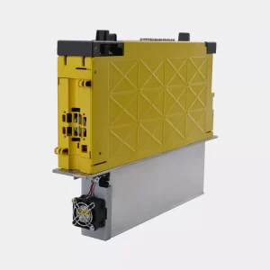
Chúng tôi có các linh kiện sẵn kho có thể xử lý máy cho khách hàng nhanh chóng hiệu quả nhất. Với đội ngũ nhiều năm kinh nghiệm chúng tôi có thể thực hiện được các công việc khó khăn của máy nhất.
Mã lỗi của bộ điều khiển Okuma 100UL:
4234 DNC Unjust request
An attempt is made to send a new command though transmission of the previous command has not been
completed. Or an attempt is made to send an abort request while data is not being transmitted.
[Character string]
Message type indication consisting of 5 characters (transfer command or sub command)
[Code] XXYYZZ:
X: Communications status
00-> Request for communications
01-> Idle status
02-> Data is being sent.
03-> Final data has been transmitted.
07-> Data is being received.
08-> An interrupt request has been sent.
09-> Abort code has been sent in response to the interrupt request.
FE-> Forced interrupt is being requested.
FF-> Forced interrupt has been performed.
YYYY: Status information
0001->Send 0002 Abort
0002->Abort
0003->Interrupt 0004 Forced disconnection
0005->Connection
[Probable Faulty Locations] Software
4235 DNC Receive message is unsame
Another command is received while sending or receiving data.
Character string Message type indication consisting of 5 characters (transfer command or sub command)
[Code] XXXXYYZZ:
XXXX Message type (type)
0000->Message other than specified 0001 ‘INI’
0002->’ALM’ 0003 ‘MER’
0004->’TER’ 0005 ‘CAR’
0006->’SRT’ 0007 ‘FIN’
0008->’STA’ 0009 ‘PST’
000A->’OPC’
000B->’OPE’
000C->’NCP’
000D->’RST’
000E->’SEL’
000F->’EXE’
0010->’DEL’ 0011 ‘DIR’
0012->’TME’ 0013 ‘DTA’
0014->’MSG’ 0015 ‘TOF’
0016->’TLM’ 0017 ‘COM’
0018->’ATC’ 0019 ‘STR’
SECTION 7 ALARM D
4187-E P-455-R2
001A->’END’
001B->’SST’
001C->’INT’
001D->’MST’
FFFF->Message type not identified
YY: Message type (classification 1)
00-> Message other than specified
01-> Request(transfer command when sending data = C)
02-> Response(transfer command when sending data = D, N)
03-> Instruction(transfer command when receiving data = C)
04-> Confirmation(transfer command when receiving data = D, N)
FF-> Message type not identified
ZZ: Message type (classification 2)
00-> Message other than specified
01-> Normal data (transfer command = D)
02-> Error data (transfer command = N)
FF-> Message type not identified
[Probable Faulty Locations]
1) CCP application software
2) Software

4236 DNC Send message is unsame
An attempt is made to send a command though transmission of another command has not been com-
pleted.
[Character string]
Type of mismatch message (transfer command or sub command)
[Code] XXXXYYZZ
XXXX: Message type (type)
0000->Message other than specified 0001 ‘INI’
0002->’ALM’
0003->’MER’
0004->’TER’
0005->’CAR’
0006->’SRT’
0007->’FIN’
0008->’STA’
0009->’PST’
000A->’OPC’
000B->’OPE’
000C->’NCP’
000D->’RST’
000E->’SEL’
000F->’EXE’
0010->’DEL’
0011->’DIR’
0012->’TME’
0013->’DTA’
0014->’MSG’
0015->’TOF’
SECTION 7 ALARM D
4187-E P-456-R2
0016->’TLM’
0017->’COM’
0018->’ATC’
0019->’STR’
001A->’END’
001B->’SST’
001C->’INT’
001D->’MST’
YY: Message type (classification 1)
00-> Message other than specified
01-> Request(transfer command when sending data = C)
02-> Response(transfer command when sending data = D, N)
03-> Instruction(transfer command when receiving data = C)
04-> Confirmation(transfer command when receiving data = D, N)
FF-> Message type not identified
ZZ: Message type (classification 2)
00-> Message other than specified
01-> Normal data (transfer command = D)
02-> Error data (transfer command = N)
FF-> Message type not identified
[Probable Faulty Locations] Software

4237 DNC Illegal sequence number
An incorrect transfer data sequence number is input while receiving data.
[Character string]
Message type indication consisting of 5 characters (transfer command or sub command)
[Code] Hexadecimal number of the transfer data sequence number
[Probable Faulty Locations] Software
4238 DNC Communication not ready
The host computer is not ready for RS232C transmit/receive.
Character string Message type indication consisting of 5 characters (transfer command or sub command)
[Code] XYYYY
X: Status (details 2 of termination status)
0-> DSR signal and CTS signal are OFF.
1-> DRS signal is ON and CRS signal is OFF.
2-> DRS signal is OFF and CRS signal is ON.
3-> DRS signal is ON and CRS signal is ON.
YYYY: Status(details 3 of termination status)
Not used
[Probable Faulty Locations]
1) The power to the host computer is not turned on.
2) Communications cable
3) RS232C board
SECTION 7 ALARM D
4187-E P-457-R2
★4239 Rotary axis parameter backup data
An error exists in the rotary axis parameter backup data.
[Code]
1-> The MAC-H Model\’s 4th axis was designated as other than B-axis by the backup data.
2-> Duplicate axis names exist in the backup data.
[Probable Faulty Locations]
1) Backup file.
2) Specification code.
3) Rotary axis parameter setting.
[Measures to Take]
1) Check the specifications code.
2) Check the rotary axis parameter setting.
4240 Spindle neutral gear select condition
4241 Tool clamp/unclamp operation condition
4242 G task stop
It is no more possible to store the machining control data in the machining control data back up file.
[Probable Faulty Locations]
1) Defective memory board
2) Defective software (The machining control data back up file is damaged.)
4243 Cross rail position auto set mode
For the machine with automatic crossrail positioning function, this alarm occurs as a warning to indicate
that the automatic positioning mode is established.
[Code]
1-> Mode ON (The machine user parameter (bit) No. 40, bit 0 is set at ON.)
2-> High-speed positioning is being executed.
3-> Precision-positioning is being executed.
4244 ther axis not indicated has been moved
While the ID/OD center was gauged by manual work gauging, an axis not used for gaging was moved.
[Index] AXIS
[Measures to Take]
This alarm can be released by moving the moved axis to the previous position, executing the clear command, or
changing modes or screens (except when the screen is changed from ID/OD CENTER to CHECK).
4245 Waiting program selection during program operation
While a file is accessed in program operation mode, “program select by schedule program”, “PPC pro-
gram select”, or “external program select” was specified by background processing.
This alarm is displayed when “0” is set at the optional parameter (bit) No. 16 bit 3.
4246 File deleted
Power is shut off during file edit (I-MAP edit, ME edit).
[Character-string] Deleted file name
For details, refer to the notice file “ERROR.BAK” in the memory (MD0:), where the deleted edit file name and
code are recorded.
[Code]
1-> Edit
2-> I-MAP edit
SECTION 7 ALARM D
4187-E P-458-R2
3-> ME edit
4248 Error File
Power is shut off during file edit.
[Character-string] Deleted file name
For details, refer to the notice file “ERROR.BAK” in the memory (MD0:), where the deleted edit file name and
code are recorded.
In the ERROR. BAK
[Code]
1-> Edit
2-> I-MAP edit
3-> ME edit
4249 Door Interlock All Axis Stop
When the operation door or front door is open, the door interlock function with D/U shutoff function dis-
plays this message, stopping all the axes.
4250 Door Interlock ATC & ATC magazine Stop
When the ATC magazine door is open, the door interlock function with D/U shutoff function displays this
message, stopping all the axes.
4251 Door Interlock APC Stop
When the APC door is open, the door interlock function with D/U shutoff function displays this message,
stopping all the axes.
4252 Please open door
When the operation door or front door open/close confirmation limit switches are at close end with the
power ON, the door interlock S function displays this message, requesting the operator to open the door
to check if the limit switches normally function.
4253 Please open ATC magazine door
When the magazine door close confirmation limit switch is at close end with the power ON, the door inter-
lock S function displays this message, requesting the operator to open the door to check if the limit switch
normally functions.
4254 Please open APC door
When the APC door close confirmation limit switch is at close end with the power ON, the door interlock
S function displays this message, requesting the operator to open the door to check if the limit switch nor-
mally functions.
4255 MOP-TOOL AUTO ENTRY
A tool with unregistered tool number is used in automatic tool data setting mode, though tool data is full.
When this alarm is displayed, the tool number is ignored; thus disabling MOP-TOOL function (aborting
feedrate override control).
[Code] Tool number
[Measures to Take]
Delete unnecessary tool data and newly register required tool data, or change the active tool number. This alarm
disappears by starting automatic tool data setting or resetting the NC.
[Related Specifications] Built-in type MOP-TOOL specification
4256 MOP-TOOL TOOL WEAR
The MOP-TOOL detected a worn tool. The worn tool is registered as an abnormal tool without stopping
the machine.
[Code] Tool number and tool classification number
SECTION 7 ALARM D
4187-E P-459-R2
[Measures to Take]
After tool change, reset the NC if the program may be interrupted. If not, select the tool data setting mode and
edit the worn tool data file by displaying the page showing “Tool wear alarm” in its abnormal tool presence/
absence column and pressing [F3] (CLEAR).
[Related Specifications] Built-in type MOP-TOOL specification
4257 MOP-TOOL OVERLOAD
The MOP-TOOL detected an overload alarm. The machine stops immediately. If “alarm stop” has been
specified at the function select parameter by parameter setting, the alarm-caused tool is registered as an
abnormal tool.
[Code] Tool number and tool classification number
[Measures to Take]
If “temporary stop” or “temporary stop + spindle stop” has been specified at the function select parameter by
parameter setting, register the alarm-stop-specified tool as an abnormal tool by pressing the abnormal tool reg-
istration switch on the addition panel before resetting NC.
After tool change, reset the NC if the program may be interrupted. To continue machining,if “temporary stop +
spindle stop” has been specified, press the spindle stop release button on the additional panel to rotate the spin-
dle. Then, edit the overloaded tool data file by displaying the page showing “Overload alarm” in its abnormal tool
presence/absence column and pressing [F3] (CLEAR).
[Related Specifications] Built-in type MOP-TOOL specification
4258 MOP-TOOL ABNORMAL LOAD SIG.
The MOP-TOOL detected an abnormal signal. The machine stops immediately. If “alarm stop” has been
specified at the function select parameter by parameter setting, the alarm-caused tool is registered as an
abnormal tool.
[Code] Tool number and tool classification number
[Measures to Take]
Take the same measures as taken on occurrence of MOP-TOOL OVERLOAD.
[Related Specifications] Built-in type MOP-TOOL specification
4259 MOP-TOOL MIN. OVERRIDE
The MOP-TOOL detected the minimum override alarm. The machine stops immediately. If “alarm stop”
has been specified at the function select parameter by parameter setting,the alarm-caused tool is regis-
tered as an abnormal tool.
[Code] Tool number and tool classification number
[Measures to Take]
Take the same measures as taken on occurrence of MOP-TOOL OVERLOAD.
[Related Specifications] Built-in type MOP-TOOL specification
4260 MOP-TOOL AE SENSOR ERROR
The AE sensor generated an error. Or, the AE sensor is not normally connected to the ADP (AD conver-
sion processor board).
The MOP-TOOL function does not operate (aborting feedrate override control).
[Probable Faulty Locations]
1) ADP board
2) AE board
3) Cable
[Measures to Take]
Replace the ADP (AD conversion processor board), AE board, or cable.
The built-in type MOP-TOOL function can be disabled by setting “1” at the NC optional parameter (bit) No. 34 bit
1 in the parameter setting mode.
SECTION 7 ALARM D
4187-E P-460-R2
[Related Specifications] Built-in type MOP-TOOL specification
4261 ADP ERROR
An abnormality occurred in the AD conversion processor board and operation check counter does not
increase its value.
The MOP-TOOL function does not operate (aborting feedrate override control).
[Probable Faulty Locations]
ADP board (AD conversion processor board) TMP board (thermal deviation AD conversion processor board)
Built-in MOP-TOOL software
[Measures to Take]
Replace the ADP (AD conversion processor board).
For the thermal deviation compensation specification, replace the TMP board (thermal deviation AD conversion
processor board).
The built-in type MOP-TOOL function can be disabled by setting “1” at the NC optional parameter (bit) No. 34 bit
1 in the parameter setting mode.
[Related Specifications]
Built-in type MOP-TOOL specification
Thermal deviation compensation
4262 Print data output
An error occurred during printing of gauging data.
This alarm is displayed when “0” is set at the optional parameter (bit) No. 16 bit 3.
[Character-string] Created file name
[Code]
1-> A print command was specified while a file is accessed in program operation mode.
2-> Creating the file ‘A.MDF’ was attempted without enough free SAT.
[Related Specifications] Print function
4263 Stroke end limit reset
A travel limit release button was pressed in manual operation mode.
4264 Axis interlock
Manual rapid traverse, cutting feed, or pulse handle feed of X, Y, or Z-axis was attempted while the B-axis
was not in any of 0°, 90°, and 180° positions.
[Index] AXIS
[Code] 5
4265 Work washing gun
An abnormal condition occurred in the workpiece washing gun.
[Code]
1-> The work washing gun normal signal has turned OFF for 1 [s] or over during operation of the gun pump.
2-> When the gun pump operation command was issued, the coolant tank level normal FS was OFF.
[Probable Faulty Locations]
1-> Malfunction of work washing gun motor
2-> Low coolant tank level
4266 Air dryer unusual
An abnormal condition occurred in the air dryer.
[Code]
1-> The dry air filter normal signal went OFF.
SECTION 7 ALARM D
4187-E P-461-R2
[Probable Faulty Locations]
1) Clogging of dry air filter
[Related Specifications] Air curtain, oil-air lubrication, linear encoder
4267 Profile generation FPU error
The machine with profile generation function is not provided with the calculation processor (FPU).
[Code]
2-> No FPU is mounted on the main board No. 2.
[Related Specifications] Profile generation specification

4268 Waiting schedule start
This alarm indicates that the machine is in the state of waiting schedule start after switching from inde-
pendent operation mode to linked operation mode.
[Related Specifications] One-touch FMS (DNC-S)
4269 ACP Version Error
The ACP board is equipped with a ROM not applicable to 3-D graphic function.
[Character-string]
The first character of the ROM version mounted on the ACP board
[Probable Faulty Locations]
The ACP board is equipped with an old version of ROM not usable for the 3-D graphic function of the machine.
[Measures to Take]
Change the ROM on the ACP board with a one designed for 3-D graphic function.
4270 No magazine tool to be selected
All the tools in the tool group specified by T, TF, TG, or TD command are faulty.
[Index] None
[Character-string]
Tool group number for TG command
Tool group number and tool serial number for TF command
[Code] Faulty tool number in hexadecimal
[Probable Faulty Locations]
All the tools in the specified tool group are faulty.
The magazine does not have the specified tool.
[Measures to Take]
Set nondefective tools with the specified group number in the magazine.
4271 Active tool is adjust tool
The selected active tool is the tool of which adjustment is set to “Y” on the TOOL ID DATA screen for tool
data setting.
[Index] None
[Character-string] None
[Code] Tool number in hexadecimal
[Related Specifications] Tool ID function


